
Marine electrification
Table of Contents
About The Author
Eirik Nesse - Director of Marine Propulsion at BOS Power.
He holds a BsC in Electronics from University of Stavanger and has over 25 years’ experience from the international telecom industry, holding various positions at the microwave supplier Nera/Ceragon, lastly as Director of Product Strategy.
Since 2018 he has devoted himself to marine electrification and is an important driver within BOS Power, assuring quality and technical excellency in marine hybrid and fully electric power and propulsion systems.

Intended audience
This paper is written for professionals within the maritime industry, who wish to gain further knowledge on technologies related to electrification for marine vessels.
It may also be read by professionals of adjacent industries who wish to get an introduction to the issues facing decarbonisation of light/fast crafts in the maritime sector.
Executive Summary
We are standing on a pivotal point in the marine industry. On the one side you have flag nations goals of reducing emissions and promotion of greener solutions at sea. On the other, you find solutions available for electrification, their benefits, and limitations.
Despite local tax and market incentives, the fact is that you can’t simply replace your diesel propulsion-system with some batteries and an electric motor.
Electric and hybrid solutions in the maritime sector requires a new set of considerations and design principles for your vessel or fleet. Furthermore, class societies are still establishing safety regulations, standards, and certifications. But our emissions must go down, and despite some limitations, electric solutions are the way forward.

Although it’s a global issue, reduction of these emissions starts with local solutions. Local governments should help drive the development and implementation of low to zero emission power solutions with the means they have available. The private sector also plays an important role adopting zero-emission solutions and adapting their operational model to this new technology.
Therefore, we strive to inform and educate on the technology available today, as well as emerging products, within hybrid and electric solutions at sea. This keeps us at BOS Power on our toes and able to provide the very best of tailored vessels, optimized for efficiency and lower emissions. It also contributes to build a knowledge base for realistic and pragmatic policy making in the future.
The future is electric and even though both the technology, regulatory bodies, and the industry must mature into this new paradigm, we are more than optimistic for what the future holds.
The sustainable solutions that we implement today are crucial for the environmental challenges we face, but also lay the foundation of new business models, industries, and services.
Introduction
Unfortunately, there is no ‘silver bullet’ in implementing a hybrid or electric propulsion power system. It’s therefore important to understand the limitations of this technology, and how to select an optimized solution.
The International Maritime Organization (IMO) as well as national governments has put forward goals for reducing the emission of Greenhouse Gasses (GHG) from the shipping sector.
In a study from 2020, IMO concludes that the share of shipping emissions in 2018 is about 2.9% of global human made emissions, in the form of carbon dioxide (CO2), methane (CH4) and nitrous oxide (N2O) gasses. These gasses come from the combustion of fossil fuels to provide power in the ship for propulsion and other use.
Although it’s a global issue, which includes the entire shipping sector (international, domestic, and fishing), reduction of these emissions requires solutions fit for the local situation.
The development and implementation of low to zero emission power solutions may be driven by financial incentives/taxation on emissions, or the incentives can be market driven. An example of market driven incentives is eco-tourism, where a trip on a quiet zero-emission sightseeing vessels offers more value to the customers compared to a more conventional diesel driven vessel.
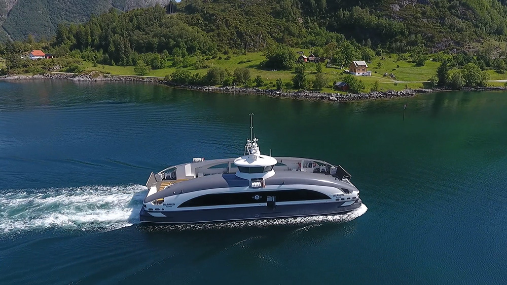
How can ship designers, owners and builders contribute to the reduction of the emissions from the operation of the vessels?
As for the road transport sector, electrification of the power systems in form of hybrid or fully electric power systems will result in reduced emissions, assuming that the energy comes from renewable sources.
In short, it currently means introducing batteries to store electric energy, while replacing some (or all) of the energy from fossil fuel.
Unfortunately, there is no ‘silver bullet’ of implementing a hybrid or electric propulsion power system. It’s therefore important to understand the limitations of this technology, and how to select an optimized solution.
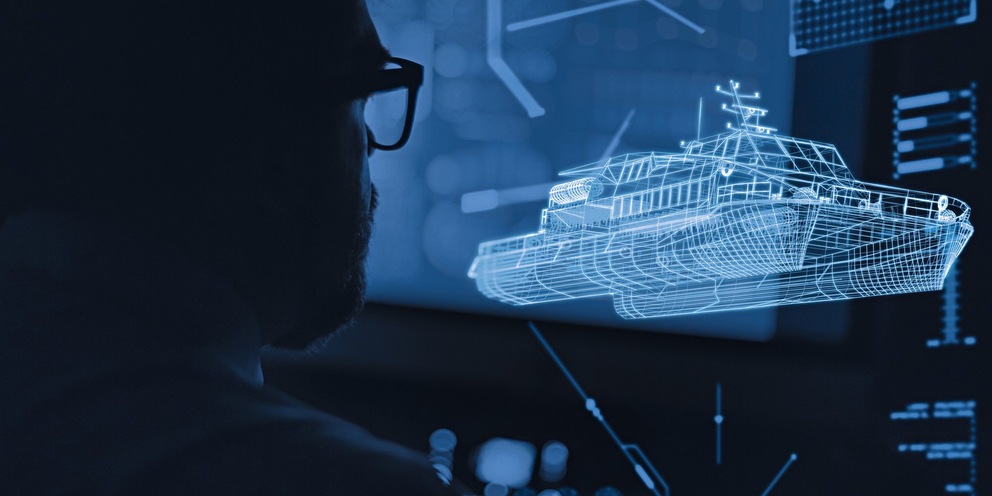
Propulsion Systems
There is no clear distinction or industry standards defining the terms hybrid and electric propulsion systems.
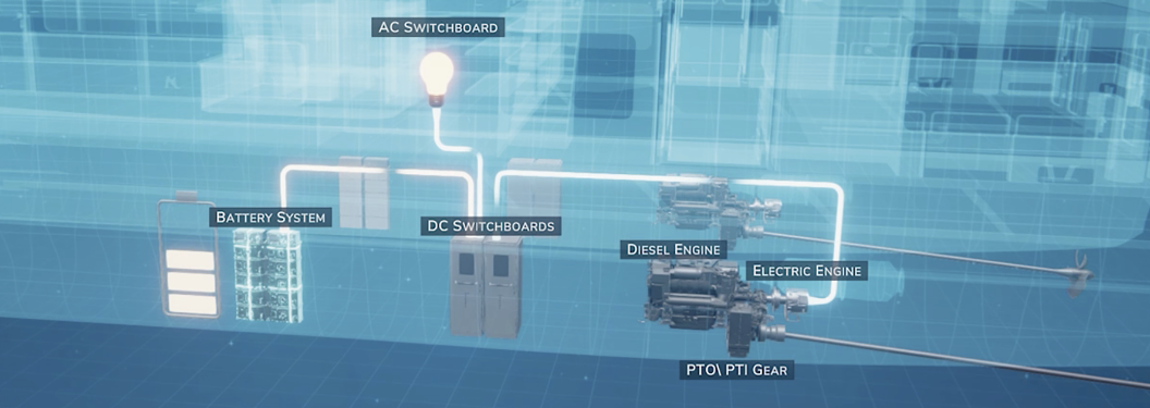
Hybrid, meaning offspring from two or more elements, clearly has both an electric part and a conventional (diesel part). However, this combination can take different forms.
BOS Power use the term ‘hybrid propulsion’ system when the propeller can be driven mechanically by a diesel engine (Diesel Mode) or by an electric motor (Electric Mode) connected to a common gear between the diesel engine and propeller line.
The propeller can also be driven by both systems in combination (Boost mode). ‘Electric propulsion’ system is used to describe a system where the propeller is driven exclusively by an electric motor (with or without a reduction gear). It’s important to understand that an electric propulsion system might still contain a generator.
In such cases it provides part of the energy for propulsion or other electric consumers onboard. This is sometimes referred to as ‘serial hybrid’ or ‘range extender’.
Such generator sets can also serve as a redundancy feature (‘take me home’), if the battery energy is drained.
What Is The Right Choice For Your Application?
Deciding on a hybrid or electric architecture depends on several key factors, where the application or the operation profile, plays a major role.
An operation profile is the description of how the vessel is operated throughout the day in terms of its power needs at different times.
A typical operation profile describes the propulsion power and duration of transit, manoeuvring/stand-by operations, and time at quay. In addition to answering the power need in operation, and consequently the energy need, it will also answer another limiting factor, which is the time and energy available for charging the batteries from the shore power grids.
As the battery, i.e., the energy storage, is THE major limiting factor in electrification, both in terms of added weight and cost for electrification of the vessels, this needs to be dimensioned correctly. Adding more energy storage not only adds cost, but also increases your energy needs.
The increased propulsion power required when you add weight, is an important consideration, particularly in fast planning vessels.
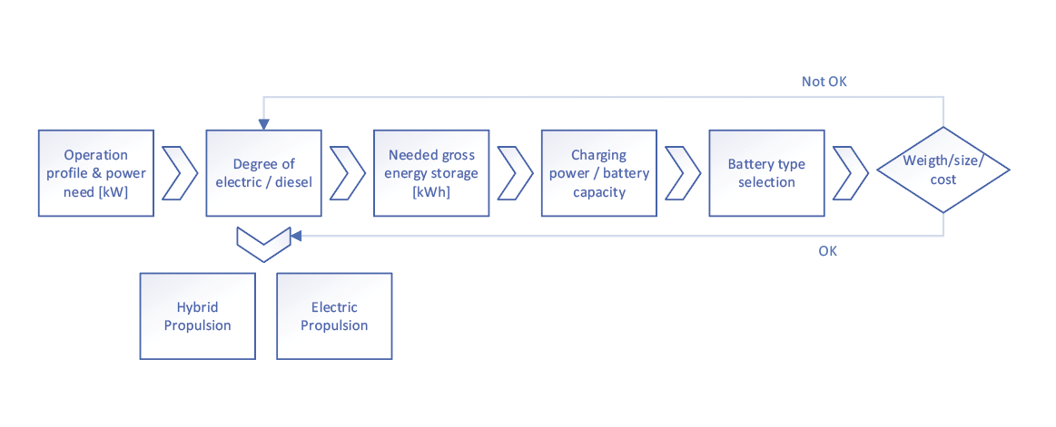
The initial selection of system architectureand battery types can be made once youhave determined the relationship between:
- Energy storage
- Power consumption (propulsion, auxiliary, and hotel)
- Charging power/energy/duration
A RULE OF THUMB
- If the application has long high-power transits with short stops/little time at quay, this points to a hybrid system. The propulsion efficiency of diesel-mechanical propulsion systems is higher than a diesel-electric system. Consequently, securing the highest efficiency of the diesel system reduces the emissions from the fossil fuel.
- If the application has shorter, or low power, transits with sufficient stays at quay to recharge the battery, this point towards an electric propulsion system.
Energy Carrier (Batteries)
The battery technology used in marine energy storage is predominantly of Li-ion type.
COMMON CHEMISTRIES
- NMC (Lithium nickel manganese cobalt oxide)
- LFP (Lithium iron phosphate)
- LTO (lithium-titanium-oxide)
While the NMC chemistry offers better energy density, it is also a bit more challenging, attributing a lower thermal stability (fire hazard). The use of Cobalt is also a challenge due to its price volatility, fragile supply chain, and more.
Marine batteries are commonly classified as either of ‘Power’ or ‘Energy’ types. This is characterized by their charge/discharge capabilities:
- ‘Power’ batteries can accept or deliver (charge/ discharge) higher power levels than ‘Energy’ batteries of the same energy storage capacity.
- ‘Energy’ batteries have a higher specific energy density (less weight) than ‘Power’ batteries of the same energy storage capacity.
However, due to limited (charge-) power acceptance they may need to be oversized in terms of nominal energy capacity. See more on C-rate below
Weight And Size
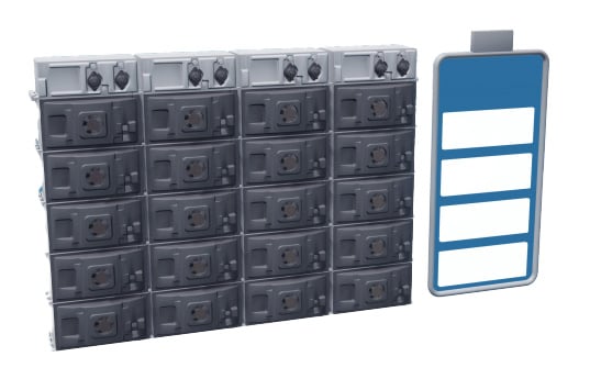
The energy density of diesel (MGO) is much higher than the energy density of marine Li-ion batteries.
While the energy density in diesel (MGO) is about 12,3 kWh/kg, the energy density of marine Li-ion batteries ranges from 0,16 kWh/kg to 0,07 kWh/ kg. However, to consider the effective weight of the energy storage system, the energy conversion efficiency must also be considered.
Internal combustion engines (ICE) burning Marine Gas Oil (Marine Diesel/MGO) fuel, have about 34 % energy conversion efficiency.
This results in a net energy efficiency of MGO of about 4,2 kWh/kg fuel at the propeller line.
To calculate the energy conversion efficiency from the battery to the output of the electric motor, we first need to determine how much of the gross energy stored in the battery we can use in operation.
The useful (out of the gross) energy capacity in a battery system is determined by the number of, and depth of, the discharge/charge cycles vs the required lifetime of the battery.

C-raten
The relationship between the maximum charge/discharge power vs the battery’s nominal energy capacity.
The relationship between the maximum charge/ discharge power vs the battery’s nominal energy capacity is expressed as C-rate;
A C-rate of 1, indicates that a battery of 100 kWh size, can deliver/accept 100kW of power, while a C-rate of 3 indicate that a 100 kWh battery size can deliver/accept 300 kW of power.
In the marine industry, C-rates between 0.7 to 3C are common.
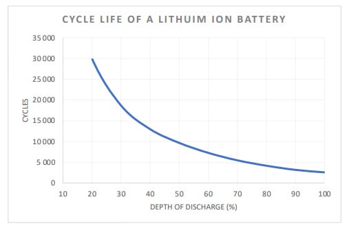
The energy storage capabilities of Li-ion batteries degrade over time and by the number of charge/ discharge cycles. It is quite common to define degradation to 80 % of the initial capacity, as End of Life (EOL). The number of charge/discharge cycles before EOL is reached depends on the Depth of Discharge (DoD) of each cycle and the battery chemistry.
An Example
Energy storage technologies are key in the transformation of the energy sector.
If a given operation profile requires the battery to be charged 5 times per day, this will give 1 825 cycles/year. The useful range of DoD for each charge/discharge cycle will be around 30 % to achieve a 10-year lifetime (18 250 cycles).
A shuttle ferry application, with frequent cycling per day, in may need a bigger gross battery size due to lower DoD tolerated per cycle versus an application with fewer cycles. This is why defining the operation profile is key to the design of the battery system.
Significant research effort and funding is put into the development of battery technologies. Energy storage technologies are key in the transformation of the energy sector, towards renewable energy sources.
Several promising battery chemistries, with increasing energy density, are being demonstrated in laboratories and universities around the world. However, bringing these into the market, in commercial products, unfortunately takes time. Moreover, the energy storage segment for the maritime sector is small compared to that of shorebased applications.
This results in lower priority for these markets. We therefore must make the best use of the current technologies; that which is proven and well known, when designing marine power systems for today.
Operation Profile
Defining the operation profile is essential to determine the optimum system design.
Both in terms of selecting the system architecture, and selection of the key component, the battery and charging system.
The operation profile is a description of the power needed at various times during the day and the time, power, and time at quay available to charge the batteries.
This will determine the net energy needed to perform the operation and the gross battery capacity required (depth of discharge), given a required lifetime of the battery system, and the C-rate of the battery (‘power’ or ‘energy’ type).
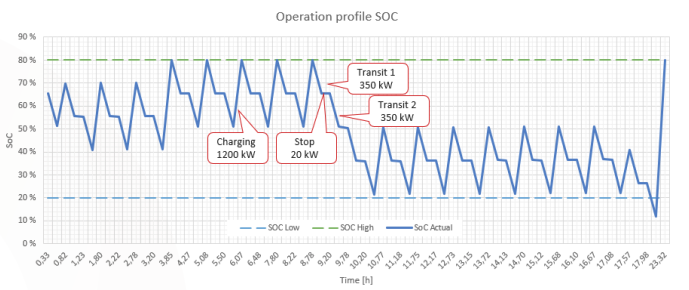
The example operation profile in Figure 3, shows that it contains 15 x 30 % DoD and 1 x 60 % DoD cycles per day. Further, this case is modelled with a gross battery capacity of 900 kWh, which means that it requires a C-rate of 1,3 during charging (1200 kW charging power).
Note that this example also poses a new challenge; The last trip of the day has a shorter charging time, resulting in a low State of Charge (SOC). This could be an issue which needs to be considered versus the capacity degradation at the EOL.
Charging Infrastructure
Bringing the electric power to the quayside
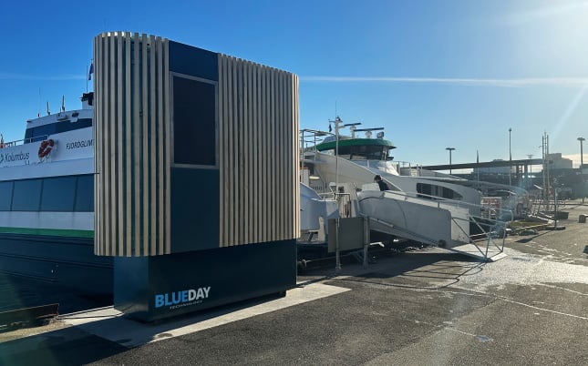
A vessel serving a high frequency route with short stops, may require a dedicated multi-megawatt supply to effectively charge the batteries in the vessel. This is a challenge due to the forementioned reasons of C-rates, Depth of Discharge, and cycle life for a battery.
MAIN CHALLENGES WITH CHARGING ELECTRIC VESSELS:
- Potentially limited available grid capacity.
- The lack of standardisation in terms of the charging interface.
- Charging infrastructure
Grid Capacity
If the operator must invest in building new or upgrading the high-power grid infrastructure, it can be a significant financial burden on the electrification project.
This is an aspect that is often overlooked. We take for granted that we have power enough in an area. That is unfortunately not the case. Whether the port or even region has the grid capacity to deliver the required charging power is a much bigger challenge and a showstopper for many operators. As you can build a charging station at the pier, constructing highvoltage infrastructure is a another thing altogether.
For vessels that only need overnight charging it’s less of a challenge. The “trickle charge” required can be facilitated at most locations. However, fully electric fast ferries, sailing high frequency routes, requires a dedicated grid connection of 3-5 MW.
Standardisation
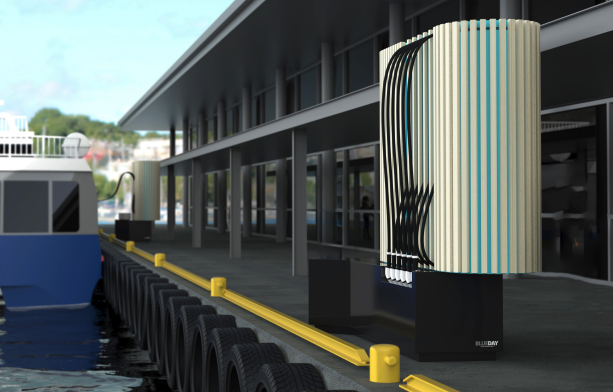
The two main solutions for charging: AC charging from the power grid on land or DC charging using charging converters onshore.
AC CHARGING FROM THE MAINLAND POWER GRID
AC charging is based on connecting the AC shore power (typically 400 VAC) to the vessel and on-board AC/DC converter(s) charge the batteries.
The available AC shore power from port authorities is typically intended for ‘cold-ironing’ and standard shore power, based on IEC 80005-3, provides about 240 kW of charging power. DC charging is based on AC/DC converters (or charging stations) located onshore.
DC CHARGING WITH CHARGING CONVERTERS ONSHORE
The CCS (Combined Charging System) is one alternative for standardized DC charging system, for charging power up to 350 kW.
The transport industry has also launched the MCS (Megawatt Charging System) which provides up to 3 MW and beyond (depending on battery voltages).
This solution is similar to automotive fast charging systems.
Regulatory / Class Requirements
Safe operation at sea is naturally of grave concern for any vessel owner/operator.
IMO and the various flag state authorities and the Class societies has over years developed a regulatory and legal framework in which ship designers and yards need to comply.
Over the last couple of years, this maritime regulatory framework has also been adopted to the introduction of electric propulsion systems, in particular for the safety of battery systems. A fire in a Li-Ion battery system can be of catastrophic nature in a vessel at sea. The potentially high energy contained in a marine Li-ion battery system, and the nearly explosive nature of thermal run-away conditions, requires strict safety considerations in the battery system’s design and installation.
Furthermore, the design of the battery room/ compartment needs to be considered with respect to fire detection and suppression, thermal control (HVAC) and off-gas ventilation.
Battery systems used in marine application needs to be type-approved by a renowned class society. Such type-approvals, among others, verifies that the battery system is free from thermal runaway propagation, i.e., that a failure/fire in a single battery cell will not cause other adjacent cells to enter a thermal runaway condition.
Control Systems / Propulsion Control
At the heart of any hybrid or electric propulsion system is the various control system(s).
The battery system itself contains a Battery Management System (BMS) function, monitoring the condition of the individual battery cells and modules.
With cell temperature and voltages and currents monitored, safe charging and discharging of the battery system is secured.
On the vessel propulsion system level, a Power Management System (PMS) together with an Energy Management System (EMS), control the power levels, voltages, and state of health of the power system’s various components. This ensures that consumers are within the designed parameters.
Key information must be easily available for the vessel operator at the bridge, and possibly the engine/equipment room(s):
- Battery energy status
- Power levels
- Remaining operation time/range
- Operational status and alarms
A control panel, or Human Machine Interface (HMI), presents the system information and status to the captain and/or the chief engineer. The control panels (HMI) may also provide input from the operator such as ‘Mode Control’, i.e.:
- Start/stop of shore power charging,
- Start/stop of diesel generator sets,
- Selection of power mode in a hybrid configuration:
– Diesel mode
– Electric mode
– Boost mode (both)
– and/or charging batteries from generator(s).
The propulsion control system (PCS) typically handles the propulsion power commands from the ship operator, like engine speed/power, propeller pitch in CPP systems, gear engage/disengage, as well as giving the operator status information.
Lastly, but not least, an alarm system (IAS) handles alarms from (all) the various ship-systems. The various control functions (PMS, EMS, PCS, IAS) may also be implemented as combined or common system(s).

A fast ferry using fast charging multiple times a day can require a dedicated grid connection of 3–5 MW.


Summary & Conclusion
We hope that this paper has provided some valuable insights to the technologies applied in electrification of power systems and the consideration need in the planning process.
Electrification, in part or complete, of the maritime vessels power systems, is a key effort towards reducing the greenhouse gasses (GHG) produced by the maritime sector.
As outlined in this paper, the technology unfortunately has limitations and is only a part of the solution for the maritime industry’s challenges. However, it’s impact will only grow with further adaption and future innovation.
Successful design and implementation of a hybrid or full electric propulsion system requires careful technical and commercial consideration, in cooperation with system experts. Additionally, the operator must consider how the system will be supported throughout the vessel’s lifetime.
Modern propulsion power systems are becoming increasingly advanced and computerized, requiring specialist competence available, in your region, for service and maintenance. Therefore, investigate thoroughly when choosing the right supplier for you or your organisation.
ABBREVIATIONS
BMS: Battery Management System
BOL: Beginning of life (Battery)
CPP: Controllable Pitch Propeller
CCS: Combined Charging System
DOD: Depth of Discharge (Battery)
EMS: Energy Management System
EOL: End of life (Battery)
HMI: Human Machine Interface
IAS: Integrated Alarm System
ICE: Internal combustion engine
IMO: International Marine Organization
kW: Kilowatt (power)
kWh: Kilowatt hour (energy)
MCS: Megawatt Charging System
MGO: Marine Gas Oil (Marine Diesel)
PCS: Propulsion Control System
PMS: Power Management System
SOC: State of Charge (Battery)
SOH: State of Health (Battery)
Get in Touch
Do you want to learn more about our solutions or discuss how we can support your next project? Our team of experts is ready to answer your questions and explore opportunities together.- Let’s talk about your needs
- Share your ideas with us
- Start building a sustainable and reliable future today